Back to Home

16 Bit

Arithmetic Logic Unit

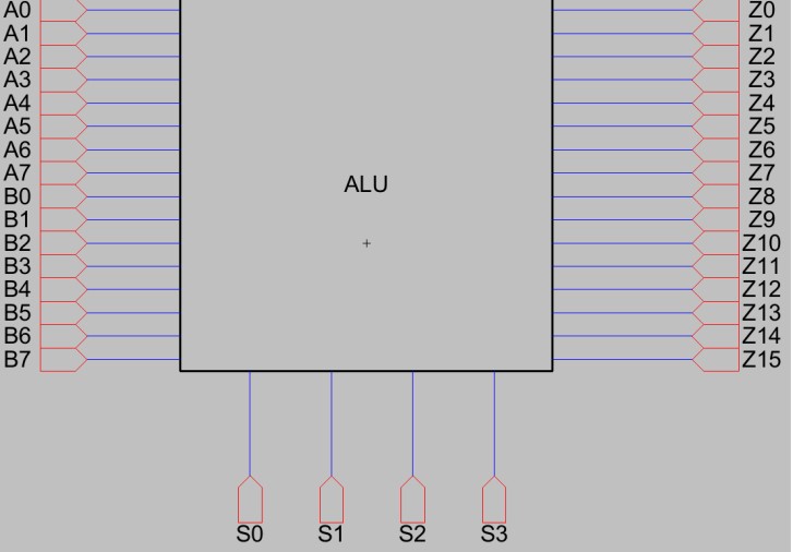
The design approach taken for the ALU was to create basic logic gates first, then from those logic gates fundamental modules will be made. Such as 2x2 multiplier, half adder, full adder and etcetera. From those basic modules I was able to create even more complex modules that will eventually be added directly to the ALU. First, I had to pick instructions and I chose to pick 8 fundamental instructions. Those instructions were multiply, add, subtract, OR, XOR, AND , shift left, and shift right. However, it should be noted that there is space for 8 more instruction integration for future use.

The multiplier used was an 8bit array multiplier. An 8 bit array multiplier works exactly like the way a human would do long multiplication. You simply add and shift one spot to the left. The adder was an 8 bit ripple carry adder, to allow for more versatility. The subtractor was made to be able to represent both positive and negative numbers. The rest of the functions are simple logic functions.
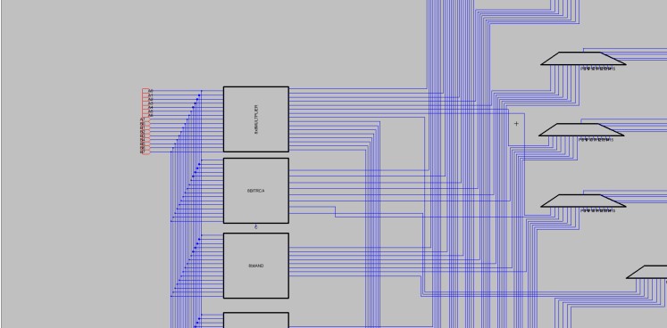
One of the novelties of my project is my ALU design. Looking alone many ALU designs can be found that use 1 bit ALUs with carry in and carry out, but I wasn’t a big fan of that design method. Instead, I wanted a method where whole modules can be added straight without having to fix the individual ALU’s used. So, I opted for a method where 16:1 multiplexers would be used for each bit to show the output based on the selection inputs given. This might be an inefficient way to do things, however it was my original way, at least to my knowledge, and it helped me increase the instructions in my ALU with ease. It should be noted that there is no clock in the ALU, however using a PISO shifter a serial output can easily be obtained to be used with clocked systems.

Project Video